How Transistors Work – A Simple Explanation :
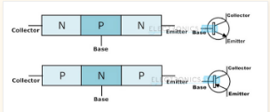
Transistors are composed of three parts a base, a collector, and an emitter. The base is the gate controller device for the larger electrical supply. The collector is the larger electrical supply, and the emitter is the outlet for that supply. By sending varying levels of current from the base, the amount of current flowing through the gate from the collector may be regulated. In this way, a very small amount of current may be used to control a large amount of current, as in an amplifier.
The same process is used to create the binary code for the digital processors but in this case a voltage threshold of five volts is needed to open the collector gate. In this way, the transistor is being used as a switch with a binary function: five volts ON, less than five volts OFF.
quantum mechanical transistor :
The quantum mechanical transistor is the equivalent of turning on a light bulb without closing a switch: Electrons "tunnel" from path to path through a barrier that, according to classical physics, is impenetrable.
The process takes place with extreme rapidity.
The term "tunneling" may bring to mind moles or the highway department, but physicists use it to describe an effect in which particles, like electrons, appear in places where by rights they should not be able to go. In effect, they have tunneled under an energy barrier the same way cars use a tunnel to appear at a new location without having to drive over an impossibly high summit. The atomic-scale effect is explained only by quantum mechanical principles.
The device, dubbed DELTT (Double Electron Layer Tunneling Transistor), offers promise of significant improvements in the speed of computers and in the accuracy of sensors.
How it works :
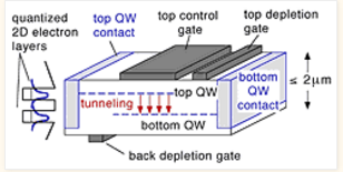
The technique relies in part upon the dual wave-particle nature of matter. In the device, two gallium arsenide layers, each only 150 angstroms thick, are separated by a 125 angstrom aluminum-gallium- arsenide barrier , the equivalent of the yards of two houses separated by a sturdy fence. Ordinarily, gallium arsenide electrons in one yard do not have the energy to climb the fence to reach the other yard. But the tiny thickness of the barrier causes the electrons to behave like waves, which can poke into the barrier.
When an electron is adjusted to have the same energy and momentum states in both regions -- something that can be done by applying a voltage to these regions -- it can pass from one region to the other without any scattering, as occurs in normal electron motion due to crystal imperfections. In effect, they tunnel under the barrier fence.
The process takes place with extreme rapidity.
The term "tunneling" may bring to mind moles or the highway department, but physicists use it to describe an effect in which particles, like electrons, appear in places where by rights they should not be able to go. In effect, they have tunneled under an energy barrier the same way cars use a tunnel to appear at a new location without having to drive over an impossibly high summit. The atomic-scale effect is explained only by quantum mechanical principles.
The device, dubbed DELTT (Double Electron Layer Tunneling Transistor), offers promise of significant improvements in the speed of computers and in the accuracy of sensors.
The very fast device may run at a trillion operations a second, as have other, more primitive tunneling devices. This is roughly ten times the speed of the fastest transistor circuits currently in use. Actual speed has not yet been measured
**The extremely fast device also runs at extremely low power tens of millivolts and microamps as compared with the few volts and milliamps needed by transistors currently in use.
The technique relies in part upon the dual wave-particle nature of matter. In the device, two gallium arsenide layers, each only 150 angstroms thick, are separated by a 125 angstrom aluminum-gallium- arsenide barrier , the equivalent of the yards of two houses separated by a sturdy fence. Ordinarily, gallium arsenide electrons in one yard do not have the energy to climb the fence to reach the other yard. But the tiny thickness of the barrier causes the electrons to behave like waves, which can poke into the barrier.
Types of transistor :
There are two main types of transistors-junction transistors and field effect transistors.
Each works in a different way. But the usefulness of any transistor comes from its ability to control a strong current with a weak voltage. For example, transistors in a public address system amplify (strengthen) the weak voltage produced when a person speaks into a microphone. The electricity coming from the transistors is strong enough to operate a loudspeaker, which produces sounds much louder than the person's voice.
Bipolar junction transistor ( BJT ) :
A junction transistor consists of a thin piece of one type of semiconductor material between two thicker layers of the opposite type. For example, if the middle layer is p-type, the outside layers must be n-type. Such a transistor is an NPN transistor. One of the outside layers is called the emitter, and the other is known as the collector. The middle layer is the base. The places where the emitter joins the base and the base joins the collector are called junctions.
The layers of an NPN transistor must have the proper voltage connected across them. The voltage of the base must be more positive than that of the emitter. The voltage of the collector, in turn, must be more positive than that of the base. The voltages are supplied by a battery or some other source of direct current. The emitter supplies electrons. The base pulls these electrons from the emitter because it has a more positive voltage than does the emitter. This movement of electrons creates a flow of electricity through the transistor.
The current passes from the emitter to the collector through the base. Changes in the voltage connected to the base modify the flow of the current by changing the number of electrons in the base. In this way, small changes in the base voltage can cause large changes in the current flowing out of the collector.
- BASE BIAS
- COMMON EMITTER BIAS
- COLLECTOR FEEDBACK BIAS
- VOLTAGE DEVIDER BIAS
FIELD EFFECT TRANSISTORS :
A field effect transistor has only two layers of semiconductor material, one on top of the other. Electricity flows through one of the layers, called the channel.
A voltage connected to the other layer, called the gate, interferes with the current flowing in the channel. Thus, the voltage connected to the gate controls the strength of the current in the channel. There are two basic varieties of field effect transistors-the junction field effect transistor(JFET)
***Most of the transistors contained in today's integrated circuits are MOSFETS's.
Applications of Transistors :
A . The transistor as an amplifier
1. A transistor can be used to amplify current. This is because a small change in base current causes a large change in collector current.
2. Example is a microphone.
3. Sound waves that are fed into the microphone cause the diaphragm in the microphone to vibrate.
4. The electrical output of the microphone changes according to the sound waves.
5. As a result, the base current is varying because of the small alternating voltage produced by the microphone.
6. A small change in the base current causes a large change in the collector current.
7. The varying collector current flows into the loudspeaker. There, it is changed into the sound waves corresponding to the original sound waves.
8. The frequencies of both waves are equivalent but the amplitude of the sound wave from the loudspeaker is higher than the sound waves fed into the microphone.
Component: Function
Microphone: To change sound signal to electrical signal
Capacitor: To block a steady current from flowing into the transistor and microphone.
Potential divider: To apply a proportion of the total voltage across the emitter-base junction so that
the junction is forward-biased.
Transistor: To amplify the input wave form.
Loudspeaker: To change the electrical signal to sound wave.
B. The transistor as switch
1. In a transistor, no current can flow in the collector circuit unless a current flows in the base circuit. This property allows a transistor to be used as switch.
2. The transistor can be turned on or off by changing the base.
3. There are a few types of switching circuits operated by transistors.
C. Light-Operated Switch
1. The circuit is designed to light the bulb in a bright environment and to turn it off in the dark.
2. One of the components in the potential divider is a light-dependent resistor (LDR). When it is placed in DARKNESS, its resistance is large. The transistor is switched OFF.
3. When LDR is lighted by bright light, its resistance falls to small value resulting in more supply voltage and raising the base current. The transistor is switched on, collector current flows and bulb lights up.
D. Heat-operated switch
1. One important component in the circuit of a heat-operated switch is the thermistor.
2. Thermistor is type of resistor that responds to the surrounding temperature. Its resistance increases when the temperature is low and vice versa.
3. When heat is applied to the thermistor, its resistance drops and a greater share of supply voltage is dropped across R. The base current increases followed by a greater increase in the collector current. The bulb will glow and the siren will sound.
4. This particular circuit is suitable as a fire alarm system.
E. Integrated Circuits
1. An integrated circuit (IC) consists of transistors, resistors, diodes and capacitors combined together in one wafer-thin chip of silicon.
2. This is one wafer-thin chip is called a microchip.
3. The microchip is only a few millimeters square with a thickness of 0.5 mm.


No comments:
Post a Comment